Posted September 11th, 2020 at 2:09 pm by Dan Musick
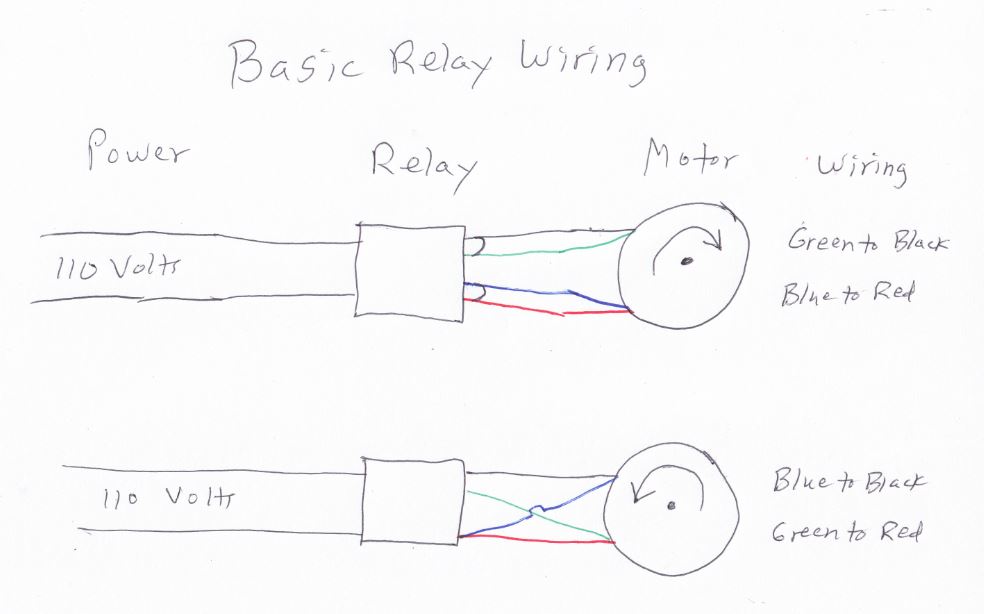
Four-wire motors
When I first got into the door business, the most common wiring for a 110-volt circuit consisted of a four-wire motor and two power leads. The two power leads ran straight to the motor. The other wires from the motor could go to either power lead. Switching these two wires would change the direction of the motor, allowing the motor to open and close a door. The new operators no longer require this type of function since they contain a LiftMaster Logic 5 control board.

The development of these systems occurred over a hundred years ago. Now, commercial operators use circuit boards to reverse motor direction and to provide a host of functions to better serve the customer. We provide the details of these functions in our new video pertaining to the LiftMaster Logic 5 control board.
The LiftMaster Logic 5 Control Board
The LiftMaster Logic 5 control board is powered by a 15-volt current supplied through a transformer in the operator. The control board outputs a 5-volt current to power the photo eyes and RPM sensor, as well as to signal the opening and closing of the door.
A Few Basic Settings
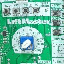
The switch at the center of the control board allows the user to switch between the different settings of the operator.

- B2 has three commands: open the door, stop the door from moving, and close the door. It works with a single button or separate open, close and stop buttons.
- C2 is similar to B2. The main difference is that the door will not close unless you hold the button down. This provides added security.
- D1 is similar to C2. In this setting, the door will not open or close unless you hold the button down. It also requires separate open and close buttons.
- E2 is almost the same as C2. The main difference is that if you stop holding down the button while the door is closing, the opener will reverse and open the door again. It also requires separate open and close buttons.
- T stands for timer. While using this setting, you can set the opener to close automatically a set time after opening.
A more detailed description of the different LiftMaster Logic 5 settings can be found in the owner’s manual. We also have a blog post about troubleshooting LiftMaster Operator error codes.
This entry was filed under How Garage Doors Work, Technical Support. You can follow any responses to this entry through the RSS 2.0 feed.


March 20th, 2024 at 9:53 am
Thank you for this information. I was actually wondering what TS, FSTS, DIAG, OPTN and PROG do and how they function as well, in Layman’s terms. I will have technicians arrive to my property some time, and wanted to understand what all of these options are in order to comprehend the information they will provide. Thank you.
April 3rd, 2024 at 7:12 am
Hello Adrian, and thank you for your question. A fuller understanding of the settings on that selector dial can be found on the 29th page of the owner’s manual. You can find the manual online, through this link: https://support.chamberlaingroup.com/s/article/LiftMaster-Logic-5-0-Industrial-Duty-Commercial-Door-Operator-Installation-Manual-1484145701310.