LiftMaster/Chamberlain Circuit Board Replacement
A common problem that can cause the failure of a garage door opener is for the circuit board to fail. When this part goes, it can cause all of the electronic components of the opener to fail, including the photo eyes, transmitters, and receivers.
Just because your opener fails to respond doesn't mean that it needs to be replaced entirely. Sometimes, a stopgap solution such as replacing the circuit board can help you to hold off on replacing the whole opener for some time yet.
This tutorial shows how to replace a circuit board on a Sears, Chamberlain, or LiftMaster opener. All three of these brands of openers are going to be virtually identical to one another. The following steps are taken from the replacement of a circuit board on a newer LiftMaster opener.
1. Before you start, make sure to unplug the opener. This is important because you could get injured by an electrical shock if something goes wrong internally on the opener.
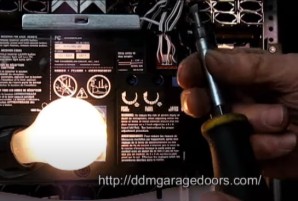
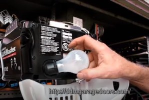
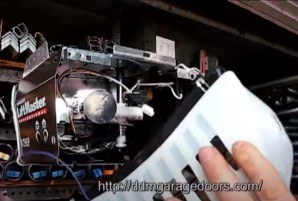
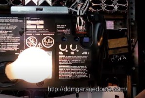
2. Next, swing the light cover open and remove the light bulb. This light bulb gets in the way of the lower screw of the front cover, and it is much easier to deal with if it is removed.
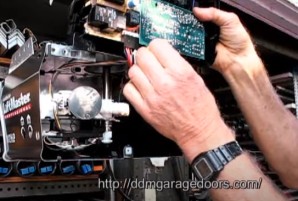
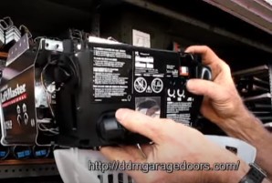
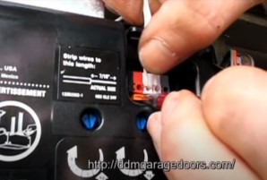
3. Before you remove the assembly on the front of the opener, you first remove the wires. To remove them, you have to push on the orange tab on the opener below the point where the wires enter to release the wires. You push in on both sides of the tab with screwdrivers, pens, or something else that can catch those tabs.
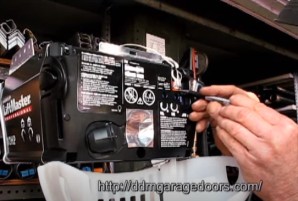
4. You can push on one tab at a time, or both tabs at the same time to make the process a little easier. If you push on both tabs, which are on the right side of all the orange tabs, both sets of wires will come loose.
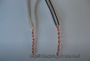
5. Two wires that are twisted together have a black stripe, and the other two wires that are twisted together are plain white wires. The last two wires left will have one wire that has a red stripe and the other that is plain white.
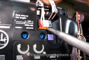
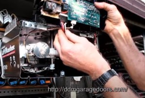
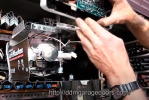
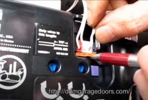
6. Once you have removed these sets of wires, you will want to take out the three screws that hold the circuit board assembly in place. There is one in the middle on the bottom, and one on the top left and one on the top right. Be careful not to lose the screws, as they are easy enough to lose if you are not careful. The new circuit board assembly may or may not have new ones.
7. When you are ready to remove the assembly, lift it up a half an inch. Make sure to catch the bottom nut as it falls when you lift up the assembly.
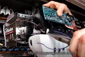
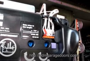
8. Do not pull the board away yet! Turn it upside down, because there are more connectors you will need to disconnect before you're ready to swap it out for the new one. You first disconnect the white connector with the smaller set of wires on it. Then, you do the same with the black connector. Now you've disconnected the old assembly completely from the opener.
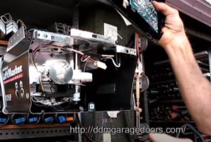
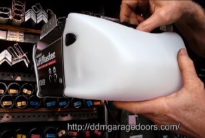
9. Next, you need to remove the old light cover, because the new assembly will not come with one. You can remove this by pushing in on the tabs with needle nose pliers, and then pulling it out. You will need do this on the other side of the assembly too.
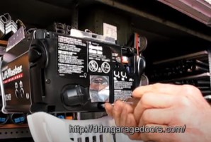
10. Now, you have the entire assembly off of the opener. It is time to bring over the new circuit board.
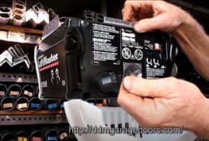
11. Before you reinstall the connectors, you will want to put the light cover back on. This is a very simple step. All you need to do is put the tabs in the same place in the new assembly as it was in the old assembly, which is on the very bottom of the assembly.
12. When you are going to reinstall the connectors, flip the new assembly upside down. This will allow you to see the two connectors. The bigger one goes to the six pins on the new assembly that correspond to the six holes in the connector. The smaller, white connector gets connected to the other connection point on the assembly.
13. Once you have done this, turn the front plate back the right way around. You will then take the whole assembly and slide it over the tabs that are on the opener end. These are the same tabs in the first step, except here you want to reconnect everything.

14. You pull out on the top and push in on the bottom, connecting the bottom first with those tabs before lining up the top. Tug on the bottom to make sure that it has clicked into the tabs.
15. Next, open up the light cover. We will now reinstall the screws that hold the front assembly in place. The threaded screws go to the top part of the assembly, and can be reinstalled with the same 1/4" nut driver that was used to remove them earlier. If you're using an impact drill, you want to take it easy so that you don't strip out the threads in those screws.
16. The smaller screw goes in the bottom middle of the assembly. The same precautions should be taken if you are using an impact drill; do not tighten with a ton of force, as you could damage the threads or crack your new circuit board assembly. A magnetic socket will make it easier to put the bottom screw back in: this bottom screw will have a different thread pattern than the other two.

17. The next step to take is to reconnect the wires. The wire with the red line on it goes on the left, and the plain white wire goes on the right. Push in on the tabs as you did before with a pen, screwdriver, or nutdriver in order to attach them.
18. The next set of wires will have different colors from the previous ones. The wire with a black line on it goes on the left, and the gray wire goes on the right.
19. After you reconnect the wires, you will tuck them behind the plastic tabs up above them.
20. Next, you will reprogram the transmitter to the receiver. To do this, you push on the "smart" button. Once the yellow light comes on, you will have thirty seconds to press the button on the transmitter. The yellow light will flash when you have connected it.
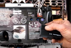
21. If you have the light bulb reinstalled, the light bulb will flash when you have programmed the transmitter. To connect your keypad, press the smart button, enter the four numbers on your keypad you want to be your code and then hold enter.
22. You will also need to re-adjust the force on your opener. You want to turn the force down to the 6 o'clock position with a screwdriver. Start there, and check the force as you open and close the opener